GD427 MK IV

GD427 MK IV
What my car should look like when finished - Stoneleigh 2015

Monday 16 January 2017

Gearbox Tunnel & Brake Connector

Since I thought that the fuel system was complete, I decided to fit the Gearbox Tunnel Sheet.  This was just set on, and fixed using M6 x 20mm Set Screws.  In previous photos, you may have noticed that I used some black sealer to put a bead down between the sheet and the chassis.  I then put on the self adhesive foam that was provided by GD.


I then mounted the brake pipe / clutch bracket.  I still need to finalise what fittings I am going to use for the clutch bleed.


I have since removed the tunnel sheet again to alter the positioning of the fule supply hose and Y-Piece as per the previous post.


Engine Wiring Harness

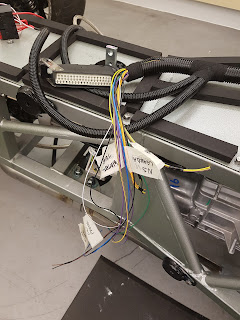
Since all the sensors have been installed, I thought I had better install the extra wires required for the harness so that the sensors could be utilised.  I laid the harness onto the engine and opened up the flexible conduit wrapping to add in the extra cores.

The wire was bought from SimtekUK, and are 1.00 sqmm in area.

I used a mixture of black insulating tape and some fibre tape to close the conduit up again.  I ran the following additional wires:

2x wires for the Oil Temperature Sensor
2x wires for the Oil Pressure Sensor
2x wires for the Coolant Temperature
2x wires for the Reverse Lockout Solenoid
4x wires for the Wideband Lambda Sensors (2x per side)
3x wires for the Oil Sump level Switch (May connect in the future)

I tried to work out how best to run the extra wires, and I decided to run them alongside the wires that go to the ECU connector.  These will be fitted with connectors once the dashboard is fitted when I work out where everything needs to go.


I also dressed the engine harness using some stainless P-Clips and some short M10 Cap Head Set Screws.


I mounted the knock sensors to each side of the block.  I used GM #12623730 sensors which are for the MK IV LS Engines.  I realise now that I need the correct mating plug for them.  I will change them when it they arrive.  The mating plug part number is GM #13580877. 

Once the starter was connected up, and the crank sensor plugged in, I fixed in the heatshield using one of the bellhousing bolts and an M10 Set Screw.


I crimped on the connectors for the following sensors:

Reverse Light Switch - Part Number Delphi 12015792
Vehicle Speed Sensor - Part Number Dorman 645-213
Reverse Lockout Solenoid - Part Number Delphi 12052646
3-Pin Sensors - Part Number GM #12551708 (CON-323 from SimtekUK)


Altogether quite neat I think.  Just neat to finalise the harness onto the fuel rails:



Fuel System - Continued

I managed to find some time over the Christmas holidays to work in the garage.  I started by installing the new fuel rails that I bought from Aeromotive.  These were easy to install, just unbolted the old ones and using the same bolts, re-bolted down.


I then removed the copper / nickel fuel pipe that I previously installed, and ran in the new PTFE lined Stainless Steel Braid hose from Goodridge (811).  Speaking with the Aeromotive Technical Department, with the twin Stealth fuel pumps that I will be using, he recommended the use of -10 hose for the supply, and -8 for the return as per the schematic below:


I initially thought about running the -10 to the centre of the bulkhead and installing the Y-piece just on the chassis (as per the below photo), but after looking at regulator placement and the ECU harness, I have decided to place the Y-Piece under the tunnel panel and have the two separate -8 hoses running to either fuel rail.


I had to remove the bracket that I have installed, and I am going to make a bracket to hold the Y-piece further back (photos to follow).  The hoses to the rear were clipped to the original mounting points and I will sort out the final run once the body is trial fitted.