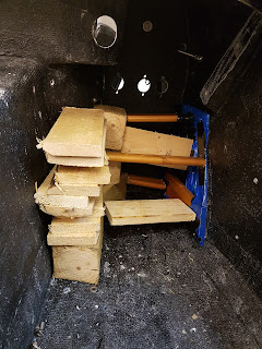
After reading up on the Innovate Lambda sensors Wideband Controller, I decided to add some length to the exhaust bung to make it the 1" as instructed.
As supplied by GD, the bungs were approx 10mm deep. I found some stainless steel ones on eBay that were 21mm long. I put them in the lathe and turned them down to 15mm to give me the overall required 25mm length. A friend then TIG welded them onto the top of the existing bung.
I had to remove the exhaust to be able to do this, and once welded, the exhaust was replaced.
GD427 MK IV
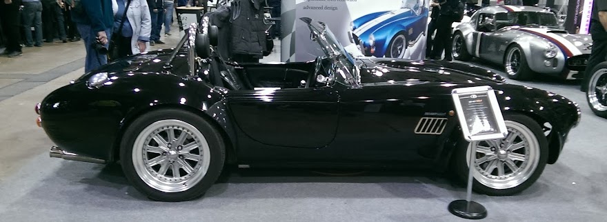
What my car should look like when finished - Stoneleigh 2015
Saturday 2 September 2017
Wiring - Continued
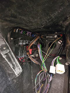
Since trial fitting the cross brace, and running the wires for the power steering, I managed to position the rear wiring loom and fix it into place.
I also had to run both fuel pump wires along side which makes it a little bulkier. I fixed the loom up under the passenger footwell using a P-Clip and then proceeded to duct tape the rest of the cable in place as it runs to the boot area. This now enables me to wire the rear lights and properly dress in the wires.
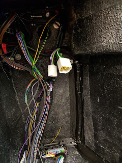
I also wired in some of my additional wires into a new 9 way round plug, and I had to colour code them to ensure they don't get mixed up.
Bodywork
I found some time in the garage so I managed to fix the boot handle and number plate light onto the boot lid. This involved measuring lots of times and lining the parts up prior to drilling. GD had already pre-installed a wire in between the boot lid skins and I managed to cut a hole behind the number plate light to enable fishing out the wire. I will fabricate a bracket to hold the number plate later.
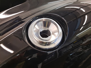
I also drilled out the hole to accept the Aston Martin style fuel filler. I will properly fit it in the coming months.
I also drilled out the hole to accept the Aston Martin style fuel filler. I will properly fit it in the coming months.
Footwell Extensions - Update
If you can recall I cut out a section for my right foot: here
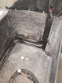
After trying the accelerator pedal in it's motions, I decided to reinforce the footwell extension that I created which removed the inner skin. I used some carbon fibre matting with resin to create a strong patch.
I cut the matting to shape, and then had to find bits of wood for props and also make a clamp frame to evenly spread the pressure. This looks like a true "Crofter" style of set-up, but it did the job perfectly.
I applied just resin around the area first and let that set. I then applied resin to the matting, both sides, before putting it in place with my clamp system. The blue plastic was used to cover the clamps so that they didn't stick to the resin.
I think all in all a good job!
Please Note: This Modification IS NOT RECOMMENDED by the factory and I have carried this out at my own risk.
Power Steering - Continued
Mark T kindly provided me with the bracing for the Corsa power steering column. He had already Engineered one for his car which can be seen on his blog.
I fitted the bracing to the car, and trial fitted the column. This then identified where the ECU could and couldn't go. Trying to avoid having to lengthen the sensor wires, and keep the ECU above the dash tray, I opted to mount the ECU to the motor itself. This involved cutting the mounting lugs off the ECU and opening out the radius to keep it closer to the motor.
I then used a length of stainless to form a clamp that bolts to the ECU mount. I place a piece of rubber under the mount which holds the ECU very tightly.
Once I trial fitted the column and everything fitted, I ran the wires for the following:
1mm² wire from the ECU round plug for the speed control from the CANEMS ecu
1mm² wire from the fuse box (5A) to supply the ECU
1mm² wire from dashboard multiplug E for RPM signal
6mm² wire from new 50A fuse
6mm² wire from -ve battery connection
I cut them to length, then crimped on new connectors bought from SimtekUK.
I have since removed the column and new bracing, and it is now being hot metal sprayed and painted prior to final fitting.
Subscribe to:
Posts (Atom)

