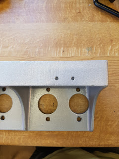
Using the engine bay ledge underside as a reference, the pedal box was mounted around 8-10mm lower that this line as Dale Cordingley did since he is roughly my size and confirms he is happy with his pedals.
I made up a cardboard template matching the alloy housing, and transferred the holes to the bulkhead before drilling with a holesaw and drill. The pedal box was positioned in such a way that the accelerator pedal could still be removed while the clutch and brake pedal remained in place.
I then drilled and tapped holes for the brake light switch mount and also for a clutch switch in case I ever need it (Cruise Control?) I will get another bracket and switch from GD just in case.
I mounted the brake and clutch pedals with the bias bar and master cylinders. I calculated that I require a 10mm spacer under the brake cylinders to prevent cutting any threads off the push rods and to maintain a slight free play of the pedal on the housing. For the clutch pedal, I require much more, however I decided to cut down the push rod by 20mm to enable a 10mm spacer to be fitted also. I have drawn up a spacer using Solidworks and a local machining company will machine some spacers for me from 10mm aluminium. I will post photos once finally assembled.
For the accelerator pedal, the GD and LS engines use a GM electronic pedal which requires a link rod to go through the bulkhead, or a re-designing of the pedal box housing to accommodate the GM pedal directly. I decided to go down the link rod route.
Firstly I cut down the GM pedal so that it can fit inside the footwell compartment above the master cylinders. I then drilled a 6mm hole to allow a rod end to be fitted. Using some blogs for information, I copied Dale's blog for a distance of 43mm down from the top of the GD pedal to gain around 100mm of travel. A 6mm hole was drilled through the GD pedal to allow a rod end to be fitted.
The tricky part was to drill a hole through the bulkhead in the correct location to allow smooth operation of the GD and GM pedals with the link rod. I used 220mm long stainless M6 threaded rod to link the two pedals with the supplied female rod ends. Once the pedal box is fully fitted, I will confirm the pedal travel and may have to adjust as required...


Blind leading the blind then ��, copying me!
ReplyDelete